Datanami
 EnterpriseAI
 HPCwire Japan
 QCwire
 HPC & AI Wall Street
Exploring new frontiers, driving higher efficiencies, and shortening time-to-production. This is the lifeblood of the oil and gas industry. Businesses in this industry are constantly finding new and more efficient ways to interpret and model data and ascertain risk through cutting-edge technologies to maintain a competitive advantage.
With ever increasing simulation model sizes, locating, extracting, and producing energy has become an extremely data-intensive undertaking. Examples of this burgeoning data demand include massive parallel computation and simulation models from geophysicists; 3D visualization and interpretation of geographic data from reservoir simulation engineers, and mining historic seismic data of current reservoirs with up-to-date algorithms. IT managers are in a continuous race to stay ahead of these massive compute and data flow tasks.

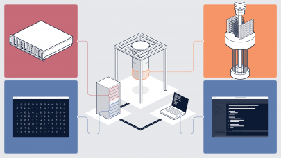
Figure 1: Visualizing oil reservoir from Engineering Simulation and Scientific Software’s Cyclops software
Deploying more servers, network storage, and workstations in the datacenter can temporarily relieve the demand for increased compute and storage capacity. However, new problems quickly arise as IT managers are confronted with the challenge of interconnecting massive amounts of devices that constantly produce and exchange huge data sets. Without a network that can maintain performance as compute and storage capacity grows, sustaining a competitive edge becomes more difficult as the time-to-result lengthens.
Traditional Datacenter Networks Become Bottlenecks
Ethernet technology has served the industry well over the past few decades. But given the growing demands on oil and gas datacenters — particularly in terms of compute, storage, and bandwidth requirements — traditional datacenter networks are becoming inhibitors in the race to stay ahead.

Figure 2: Traditional network diagram
These key inhibitors include:
- Spanning Tree Protocol (STP)
STP leads to an underutilized network infrastructure. It was designed to prevent looping traffic in a traditional multi-tier network. STP ensures all network forwarding paths are in a primary-backup model. The end result is a very high rate of inefficiency with up to 50 percent of the available network bandwidth sitting idle in a hot-standby mode.

Figure 3: Spanning tree network diagram
- New oil and gas industry computing models require hundreds, if not thousands, of compute servers with heavy server-to-server as well as server-to-storage traffic patterns. STP not only leads to a high level of inefficiency, but its heavyweight (e.g., slow) control protocol discourages network architects from designing large networks for fear of paralyzing the network when the STP protocol is invoked. Moreover, network architects are conditioned to design around the problem by segmenting their datacenter network in a collection of smaller “pods” or clusters that lead to inefficiencies in performance and higher network equipment costs.
- Best Effort Delivery Mechanism Leads to Data Loss
Ethernet relies on “best-effort” data transmission. Traditional network devices are assigned buffers to deal with temporary network bursts. Once the buffer is exhausted, the network switch simply drops further incoming packets and relies on higher level networking protocols to recover and retransmit. Ethernet’s approach, while sufficient for normal day-to-day IT applications and traffic patterns, is grossly inadequate for large-scale computing models in the oil and gas industry. Compute servers and storage infrastructures drive increased model sizes and data sets at high speed. Geophysicists and network architects have found that these heavy traffic patterns result in constant data loss that requires additional computing and storage cycles just to recover from the network data loss.
- Store-and-forward Switching Leads to Unpredictable Jitter
Traditional Ethernet switching infrastructures are built on “store-and-forward” architectures. Incoming traffic is stored, analyzed, and forwarded to the destination. Each and every forwarding stage of the network repeats this forwarding process as data traffic propagates through the network. Due to the variable size of network data sets, a traditional Ethernet network always has performance variability or “jitter” (the variance in latency among all data flows). While simple and fast enough for traditional IT applications, such as PC desktop connectivity, jitter actually causes unpredictable performance degradation in the oil and gas datacenter.
Typical applications in oil and gas — such as simulation, location assessment, risk management, visualization and others — all require data input from a network storage source which feeds into a Message Passing Interface (MPI)-based parallel application environment. These MPI applications are designed to constantly process data sets with variable sizes in real-time, and in a parallel and pipe-lined computing environment. Due to the unpredictable nature of traditional Ethernet jitter, these parallel oil and gas applications are forced to spend significant idle cycles waiting for the completion of the slowest process before moving to the next stage of their pipe-lined computing process. The end result is longer time-to-result.
All in all, it is clear that the network interconnect is lengthening the oil and gas industry’s time-to-result. A new architecture and a new delivery mechanism are needed. Both must be ubiquitous, standards-based, and low-cost while driving a higher level of performance. In this way, oil and gas datacenters can facilitate faster time-to-result.
Ethernet Fabrics Break the Bottleneck
While traditional datacenter networks are becoming inhibitors for oil and gas companies in their race to stay ahead, Ethernet fabrics present a new way for oil and gas companies to speed time-to-result and maintain a competitive edge.
An Ethernet Fabric is a purpose-built Ethernet solution for datacenter networks that enables a high-speed, ultra-low latency, loss-less, and scalable network. An Ethernet fabric can be the basis for one switch (top-of-rack or chassis) or multiple interconnect fabric switches. The Ethernet fabric offers full cross-sectional bandwidth, and allows the compute and storage servers to maximize aggregate compute power in orders of magnitude cost-effective way.
An Ethernet fabric solution offers:
- Non-blocking, full cross-sectional bandwidth.
- Loss-less packet delivery.
- Ultra-low latency.
- Solution prices far less than traditional network solutions.

Figure 4: Ethernet fabric topology
Ethernet fabrics overcome the limitations of traditional datacenter networks in the following ways:
- No Spanning Tree Protocol (STP)
There are now new standards-based Ethernet solutions that use the standard Ethernet frame format and forwarding technology, but are not bounded by STP. These solutions are known as Ethernet fabrics. All available network links within the fabric are active forwarding paths. The control plane-intensive STP convergence and recovery that easily paralyzes traditional networks is not an issue for Ethernet fabrics. All investments in the fabric (i.e., all network ports and links) are put to work in contrast to older solutions that utilize a primary-backup or 50 percent utilization scheme. Ethernet fabrics maximize customers’ investments by utilizing all available network connections. This yields maximum throughput and aggregate bandwidth.
With faster throughput and more aggregate bandwidth, geophysicists can further push the boundary of model sizes and run a higher number of MPI applications while shortening their time-to-result.
- Lossless Network Architecture
Ethernet fabrics will support standards-based 802.1Qau congestion notification. One supplier of these new fabrics also has full visibility of network congestion and utilization, and makes the best forwarding decision by selecting the path with the lowest latency and lowest jitter in real-time. Note that this particular fabric does not need STP. Therefore, it has all available paths for traffic forwarding. This is especially critical when latency is building along a specific path – a proxy for emerging congestion. By constantly measuring the latency of all paths in real-time, the fabric forwards around the emerging congestion. In the event of egress congestion, the fabric automatically signals the sending ingress port to slow down the incoming traffic until the receiving egress congestion is cleared. This new fabric approach leads to a much higher level of application and storage performance because no packets are lost, nor is there a need for data retransmission.

Figure 5: One vendor’s unique Ethernet fabric implementation
- Many oil and gas datacenter applications process multi-terabytes of data at any given time. Dedicated storage area networks (SAN) or network attached storage (NAS) devices are typically deployed in order to provide storage on demand. Separate Ethernet-based network infrastructures are used for server connectivity. Interconnecting between the loss and delay-sensitive storage and the best-effort Ethernet networks has been a network design challenge for oil and gas network architects. Data loss in network storage will most likely require costly and time-consuming delays (e.g., as a result of file system retransmit). Ethernet fabrics can ensure no data loss throughout the fabric. Storage and compute traffic can be transmitted throughout the entire fabric without packet loss, thereby ensuring higher performance and reliability. As a result, a unified fabric for server and storage connectivity can be achieved with high throughput, low latency, and high aggregate bandwidth.
- Low Latency Switching
Traditional store-and-forward switching designs can lead to unpredictable delay and jitter. Ethernet fabrics are based on switching technology that delivers “cut-through” data forwarding. All packets are instantly forwarded the moment their destination can be determined without incurring the unnecessary delays found in store-and-forward approaches. Cut-through switching designs ensure low latency across network infrastructures, regardless of the application and storage and data set sizes.
Oil and gas MPI applications are deployed on thousands of processors in a parallel and pipelined computing fashion to reduce total time-to-result. Cut-through switching ensures network transmission delays are minimized and always predictable. In contrast to the unpredictable nature of a store-and-forward switching environment, cut-through switching will make oil and gas application job scheduling simpler and more efficient, resulting in faster application performance.
- CLOS Architecture and Multi-pathing
Unlike traditional multi-layer designs which are oversubscribed on each and every layer, Ethernet fabrics are based on a two-staged CLOS, sometimes called Fat-Tree, architecture. Ingress and egress bandwidth is equal in CLOS design ensuring wire-speed performance regardless of fabric size.

Figure 6: CLOS topology diagram
- However, due to the variance in traffic patterns and loads emanating from the different applications using the fabric, temporary congestion can arise. Traditional Ethernet designs rely on a large amount of buffers in their network switches to mitigate this short-term congestion. But the end result is increased transmission time, and increased application and network performance variability or jitter. Ethernet fabrics, on the other hand, have all transmission paths available to all destinations. And the innovative Ethernet fabric implementation always selects the path with least latency, thereby automatically load balancing the entire fabric and minimizing application and network jitter.
With predicable latency (i.e., low jitter) and maximum bandwidth, Ethernet fabrics deliver a high-speed “pipeline” that is now essential for demanding oil and gas datacenter applications.
About the Author
Joseph Ammirato is vice president of marketing for Woven Systems. You can send him an email at this address: [email protected].