Datanami
 EnterpriseAI
 HPCwire Japan
 QCwire
 HPC & AI Wall Street
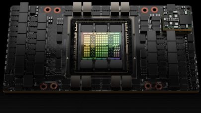
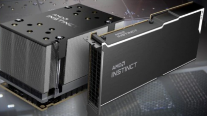
The critical driver for any AI or HPC cluster is the ability to fit to a usage model that requires continuous computing throughput across the entire system. HPC and the latest AI architectures are characterized by clusters and their nodes running at 100% utilization for sustained periods. Further, as any such application is always compute limited, cutting edge AI and HPC requires the highest performance versions of the latest CPUs and GPUs. This means the highest frequency offerings of processors such as NVIDIA’s V100 GPUs and Intel’s Xeon Scalable Processors (Skylake). Indeed, the highest performance versions also means the highest wattages.
The wattages for NVIDIA’s Volta V100 GPU are currently at 300 watts and both Intel’s Xeon Scalable Processors (Skylake) CPU and Xeon Phi (KNM) MIC-styled GPU & have been publicly announced at 205 and 320 watts, respectively.
These chip wattages translate into substantially higher wattage densities at both the node-level and rack-level not simply because of the component wattages alone but also due to the requirement for the shortest possible signal distance between processors, GPUs, switches both in and between cluster racks. For HPC workloads, overall computing throughput is also constrained by signal delay both in the spatial and time domains. These factors are driving cluster racks well beyond 50kW to 80kW or higher.
 Racks with air heat sinks struggle to handle the heat to maintain this maximum throughput and CPU throttling occurs due to inefficient air cooling. Particularly for HPC sites, reducing rack densities can mean increasing interconnect distances resulting in greater latency and lower cluster throughput. As a result, liquid cooling is required for the highest performance AI and HPC systems.
Implementation of liquid cooling at its best requires an architecture that is highly reliable, flexible to a variety of heat rejection scenarios, adaptable to the underlying compute and interconnect architecture and is not cost prohibitive. All of these factors must be addressed by the liquid cooling architecture so that compromises need not be made in the compute architecture.
From a reliability standpoint, there are a number of cooling elements to consider. The most important factor is to have very low pressures throughout the system (e.g. 4psi) both in the node and at the rack level which also addresses the cost issue in not requiring high-pressure components and allows for higher densities. Additionally, redundancy in the cooling architecture is needed to mitigate any impact of single point failure and to allow for component replacement during normal scheduled down-time. Finally, a robust monitoring and alarming system is needed to monitor the cooling system and anticipate potential issues over time.
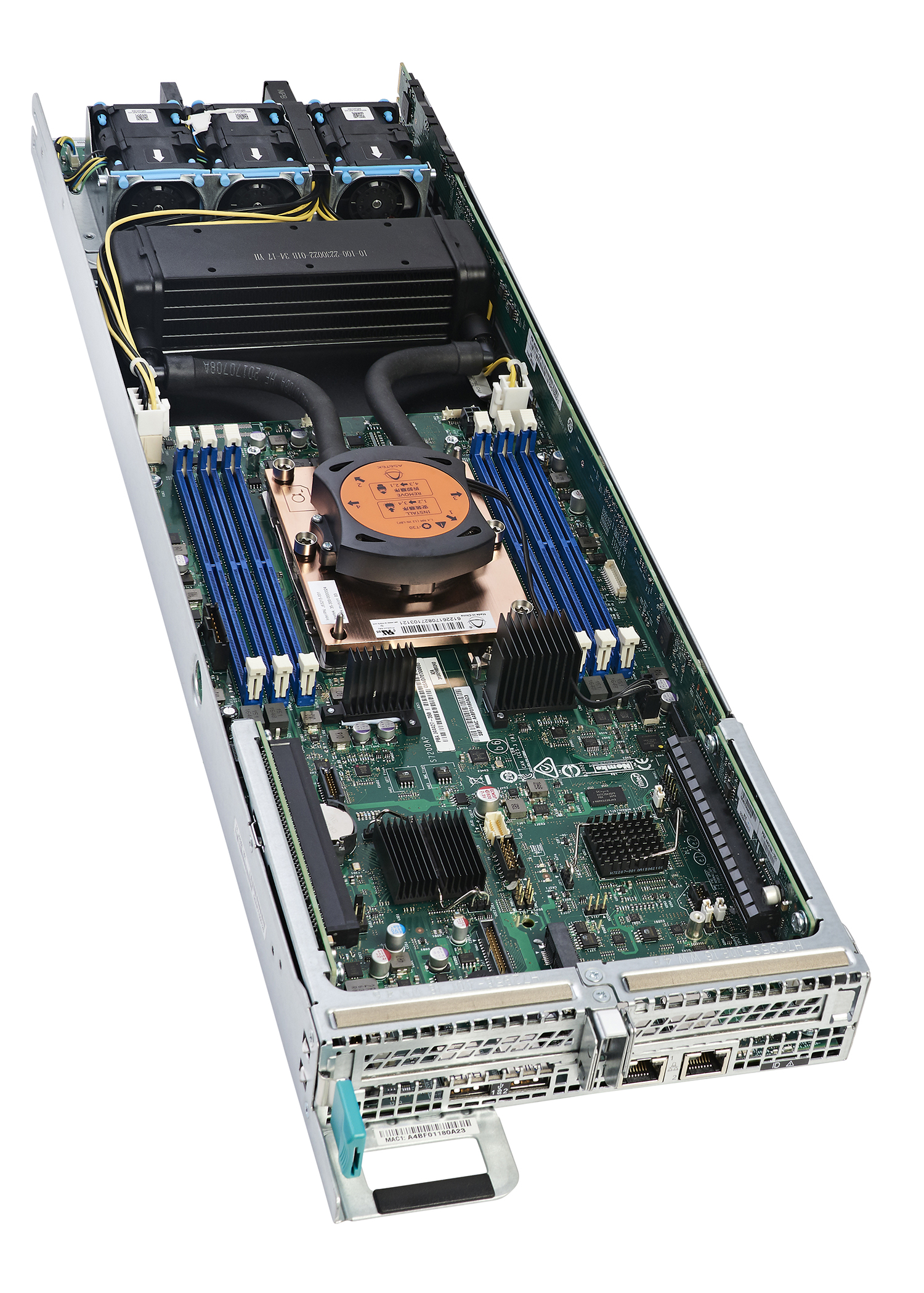
Adaptability of the cooling architecture is often overlooked largely due to the historical approach of liquid cooling related to the use of high-pressure pumping systems that take a one-size-fits-all approach. With Asetek’s distributed architecture in contrast, coolers (integrated pumps/cold plates) are placed within server or blade nodes, and these coolers replace CPU/GPU air heat sinks in order to remove heat with warm water. This has numerous advantages.
Heat capture with distributed pumping liquid cooling combined with options for heat rejection into either data centre air or facilities liquid seen in Asetek’s architecture provides a flexibility to address high-wattage on an as-needed basis. The Asetek architecture heat rejection options provide adaption to existing air-cooled data centers and to liquid-cooled facilities.
 Adding liquid cooling with no impact on data center infrastructure can be done with Asetek’s InRackLAAC™, a server-level Liquid Assisted Air Cooling (LAAC) option. With InRackLAAC the redundant liquid pump/cold plates are paired with a shared HEX (radiator) in the rack. Via the HEX the captured heat is exhausted into the data center. InRackLAAC places a shared HEX with a 6kW 2U chassis that is connected to a “block” of up to 12 servers. Existing data center HVAC systems handle the heat.
Multiple such computing blocks can be used in a rack. InRackLACC allows incorporation of the highest wattage CPUs/GPUs and additionally racks can contain a mix of liquid-cooled and air-cooled nodes.
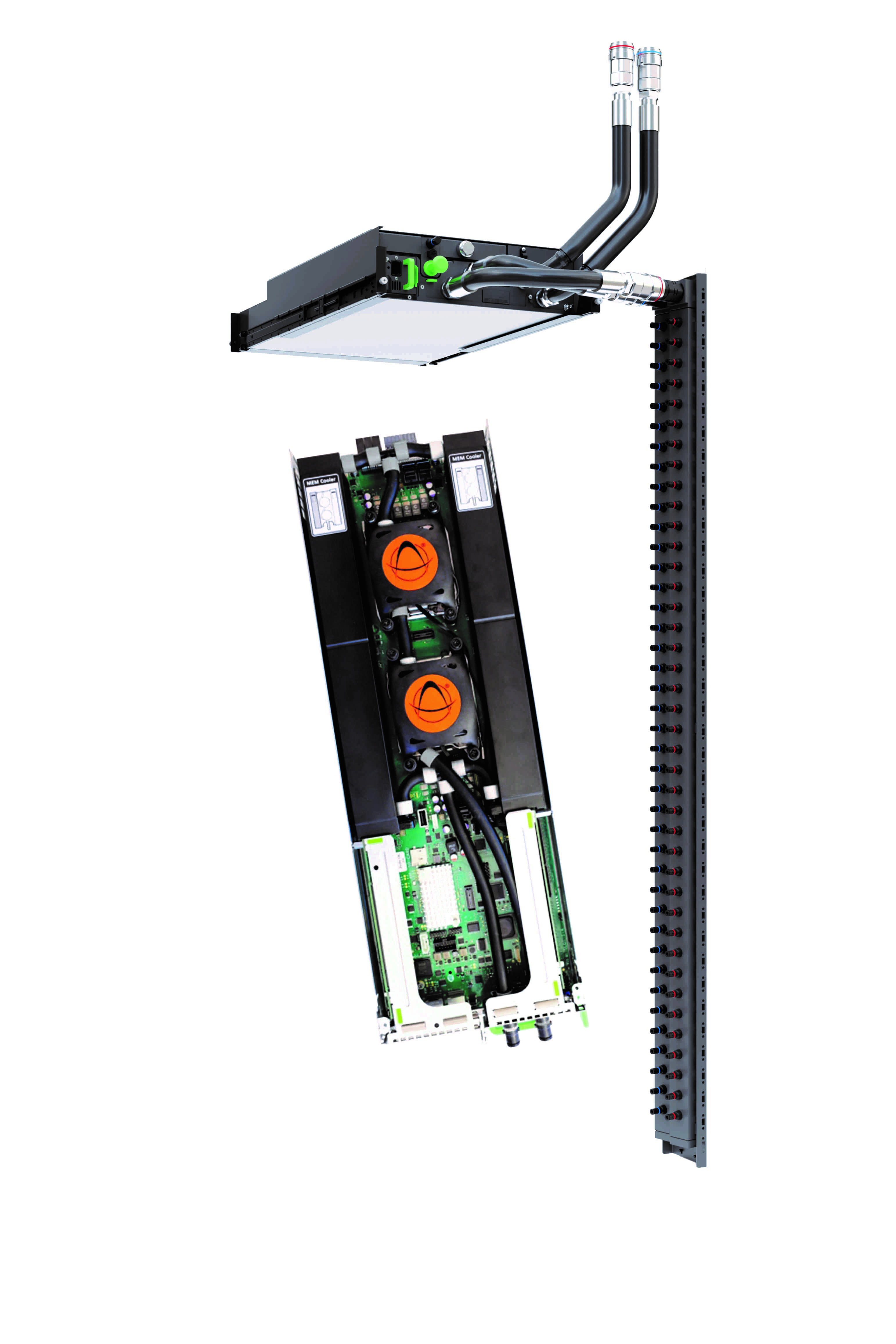
When facilities water is routed to the racks, Asetek’s 80kW InRackCDU™ D2C (Direct-to-Chip) can capture 60 to 80 percent of server heat into liquid, reducing data center cooling costs by over 50 percent and allowing 2.5x-5x increases in data center server density. Because hot water (up to 40ºC) is used to cool, it does not require expensive HVAC systems and can utilize inexpensive dry coolers
With InRackCDU the heat collected is moved via a sealed liquid path to heat exchangers for transfer of heat into facilities water. InRackCDU is mounted in the rack along with servers. Using 4U, it connects to nodes via Zero-U PDU style manifolds in the rack.
Asetek’s distributed pumping architecture at the server, rack, cluster and site levels delivers flexibility in the areas of heat capture, coolant distribution and heat rejection that other approaches do not.
Visit Asetek.com to learn more.